Table of Contents
- Documentation
- General Information
- Transform Sensor
- Collision sensor
- Overlap sensor
- Radar sensor
- Lidar sensor
- Camera sensors
- Spawning sensor
- Exporting Sensors and vehicles with sensors
- Using Camera sensors to gather synthetic data (DataCapture)
Documentation
| Topic | Link |
|---|---|
| Getting Started | Getting Started |
| Using the Simulator | Using the Simulator |
| Using Vehicles | Using Vehicles |
| Using Walkers | Using Walkers |
| Sensors | Sensors |
| Data collection | Data collection |
| Creating own maps | Creating own maps |
| Building from source on Linux | Building on Linux |
| Building from source on Windows | Building on Windows |
| Installing on Linux | Installing on Linux |
| Installing on Windows | Installing on Windows |
General Information
All sensors are Unreal Engine Actors implemented in C++. They all derive from the ASensor base Actor.
Each sensor publishes its own data and message type to its own ROS topic. The ROS topic name is the same as the sensor ID. You can query all active ROS topics with the command below from the terminal.
Transform Sensor
The Transform Sensor is automatically created and attached to each Vehicle. It operates entirely on the CPU with minimal impact on overall CPU load.
This sensor remains invisible in all the UI's, cannot be deleted, and will automatically be destroyed when the Vehicle is removed.
Note: This topic is for information only. The simulator does not subscribe to it. To control the Vehicle through ROS see Using Vehicles.
This sensor publishes two types of messages:
Parent Actor Transform
Publishes the Transform component data of the parent Actor, including Translation and Rotation information, using the geometry_msgs/Transform message format.# Transform topic naming# /Agrarsense/Sensors/ID/transform# For example/Agrarsense/Sensors/forwarder/transform/Agrarsense/Sensors/harvester/transform/Agrarsense/Sensors/drone/transform# If you echo the topic the data should look like this:translation:x: 85487.27554432102y: 70866.33801191082z: -2485.388920965257rotation:x: 0.03496819132314945y: -0.007906817838893326z: 0.0065712834606426775w: 0.9993355422784332GPS Coordinates
Publishes the GPS data in std_msgs/String format, structured as a comma-separated string with the following order:Latitude, Longitude, Altitude
Note: GPS coordinates are only published in maps where map has been georeferenced using Unreal Engine Georefering plugin (Suomi and Vindeln map).
# GPS topic naming# /Agrarsense/Sensors/ID/gnss# For example/Agrarsense/Sensors/forwarder/gnss/Agrarsense/Sensors/harvester/gnss/Agrarsense/Sensors/drone/gnss# If you echo the topic the data should look like this:64.271063, 19.777301, 291.649881
Collision sensor
Collision sensor is created automatically for each Vehicle. Collision sensor runs enterily on the CPU and adds minor CPU load.
Collision sensor publishes its collision data as string with the following format:
Overlap sensor
Overlap sensor is created automatically for each Vehicle and Spectator actor. Overlap sensor runs enterily on the CPU and adds minor CPU load.
This sensor remains invisible in all the UI tools, cannot be deleted, and will automatically be destroyed when the Vehicle is destroyed.
This sensor can be used to detect when Vehicle (or Spectator) starts and ends overlapping surrounding objects such as other vehicles, walkers, trees, rocks etc. Only StaticMeshComponent, InstancedStaticMeshComponent or SkeletalMeshComponents are checked
Forwarder and Harvester automatically create 1 overlap sensor which bounds area is 50 meters by default. See picture below.

Drone automatically creates 2 Overlap sensors, inner and outer Overlap sensoprs. These can be configured when spawning Drone via Json file. The outer Overlap sensor bounds ais 25 meters and inner 8 meters by default.

The output of the sensor is simple string ROS message with following format:
You can visualize all Overlap sensors bounds with following ROS commands. This is only visible with the Spectator camera. See Using the Simulator for how to use ROS commands.
Note. This also enables Spectator overlap sensor visualization.
You can also change the bounds area and relative offset with following ROS commands, where "forwarderoverlap" here is the ID of the sensor.
Radar sensor
Unreal Linetrace based Radar sensor.
Radar sensor runs enterily on the CPU and adds minor to medium CPU load.
Radar sensor parameters:
| Parameter | Type | Default | Description |
|---|---|---|---|
Range | float | 100.0 | Radar maximum range in meters. |
HorizontalFOV | float | 30.0 | Radar horizontal field of view in degrees. |
VerticalFOV | float | 30.0 | Radar vertical field of view in degrees. |
PointsPerSecond | int | 1500 | Number of points per second to send from the radar. |
SendDataToRos | bool | true | Indicates whether to send radar data to ROS. |
VisualizeRadarHits | bool | false | Indicates whether to visualize radar hit locations. |
Lidar sensor
Unreal Linetrace based Lidar sensor.
Lidar sensor runs enterily on the CPU and adds medium to high CPU load and minor GPU load if VisualizePointcloud is set to true.
Depending on sensor parameters and PC's CPU, The simulator should be able to handle 3+ Lidar sensors at the same time without significant performance degradation.
Lidar sensor point cloud visualization (Unreal Niagara particle system) only shows up on Spectator camera.
For other cameras, this visualization is hidden by default. For Lidar sensors with high PointsPerSecond value, it's recommended to set VisualizePointcloud to false to save performance. Also Note that each point cloud visualization lasts for 1 second, so multiple point clouds may overlap.
If ROS is setup correctly and it's active, each Lidar sensor creates its own ROS topic and publishes pointcloud data into the topic.
The simulator also creates a secondary ROS topic, Agrarsense/Sensors/lidars_combined, where the combined point cloud from all Lidar sensors is sent. Lidar sensor can be excluded from this by setting SendDataToCombinedROSTopic to false.
UseLidarNoiseModel is dependent on the Simulator Weather settings. Noise model is only active when following Weather conditions are met:
- Temperature is below zero.
- Precipitation is higher than zero.
UseLidarNoiseModel refers to a specific noise model developed by LUAS. DistanceNoiseStdDev and LateralNoiseStdDev adds additional noise to the line trace results.
When SavePointcloudWithoutNoiseModel is to to true, point clouds without the noise is only saved when either DistanceNoiseStdDev is higher than 0.0 or LateralNoiseStdDev is higher than 0.0 or when UseLidarNoiseModel is set to true and simulation weather parameters support usage of the lidar noise model formula.
When SendDataAtRotationFrequency is set to true, the sensor simulates a full point cloud at the specified RotationFrequency. For example, at 10 Hz, the sensor generates 10 point clouds per simulation second. If this is set to false, a part of the point cloud is sent/saved to ROS/disk every simulation frame. The sensor is also optimized for SendDataAtRotationFrequency being true.
Note. SaveDataToDisk works asynchronously as is not guaranteed to be saved in the same frame.
Lidar Sensor parameters:
| Parameter | Type | Default | Description |
|---|---|---|---|
Channels | int32 | 32 | Number of channels. |
Range | float | 120.0f | Lidar max range in meters |
PointsPerSecond | int32 | 655360 | Number of points per second |
RotationFrequency | float | 10.0f | Sensor rotation frequency / frame rate. |
UpperFovLimit | float | 22.5f | Angle in degrees of the highest laser. |
LowerFovLimit | float | -22.5f | Angle in degrees of the lowest laser. |
HorizontalFov | float | 360.0f | Horizontal field of view in degrees. |
DistanceNoiseStdDev | float | 0.00f | Controls the amount of variability or "spread" in the distance measurements due to noise. A higher value means more noise. |
LateralNoiseStdDev | float | 0.00f | Controls the amount of lateral noise applied perpendicular to linetrace, affects randomly in either horizontal or vertical direction. |
Semantic | bool | false | Whether this lidar is Semantic. When this is true, each lidar hit is colored based on hit object. See labels and colors below. |
UseComplexCollisionTrace | bool | true | Whether to use complex mesh collision trace. Turning this to false is more peformant but results in linetraces to use simple collision. |
UseTerrainSnowHitAdjustment | bool | true | Whether to use linetrace terrain snow hit adjustment in the Lidar processing (simulate if Lidar linetrace "hits" snow layer). |
SendDataAtRotationFrequency | bool | true | Whether to send/save data every simulation frame or at the specified RotationFrequency. |
SendDataToCombinedROSTopic | bool | true | Whether to send this lidar data to a combined ROS topic. |
SaveDataToDisk | bool | false | Whether to save this lidar data to disk in .ply format. Point cloud will be saved to SIMULATION_ROOT/Data directory. |
SendDataToROS | bool | true | Whether to send this lidar data to a ROS topic. |
VisualizePointcloud | bool | true | Whether to visualize this Lidar sensor with a Niagara particle system. |
UseLidarNoiseModel | bool | false | Should LUAS snowfall Lidar noise model be used. Weather parameters (temp, precipication particle size) affect lidar noise model formula. |
SavePointcloudWithoutNoiseModel | bool | false | Should save point cloud without lidar noise model applied. Note. Both UseLidarNoiseModel and SaveDataToDisk need to be true. |
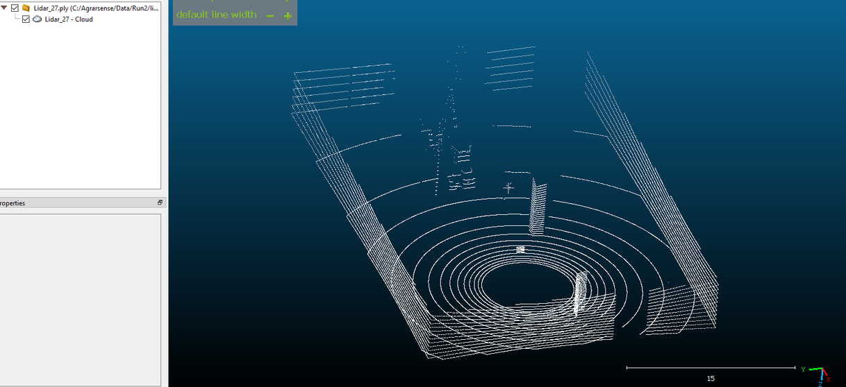
Saved pointcloud visualized in CloudCompare software.
if Semantic parameter is enabled, linetrace checks the hit component and changes adjusts point color based on hit object. Lidar semantic colors are as follows:
| Label | Color |
|---|---|
None | 0, 0, 0 |
Other | 255, 255, 255 |
Terrain | 192, 96, 192 |
Prop | 128, 64, 128 |
Pedestrian | 220, 20, 60 |
Animal | 255, 0, 255 |
Vehicle | 0, 0, 142 |
Foliage | 107, 142, 35 |
Birch | 0, 255, 0 |
Pine | 0, 128, 0 |
Spruce | 0, 192, 0 |
Alder | 0, 255, 128 |
Willow | 0, 255, 255 |
Snowflake | 255, 255, 0 |
Road | 169, 169, 169 |
Building | 0, 0, 255 |
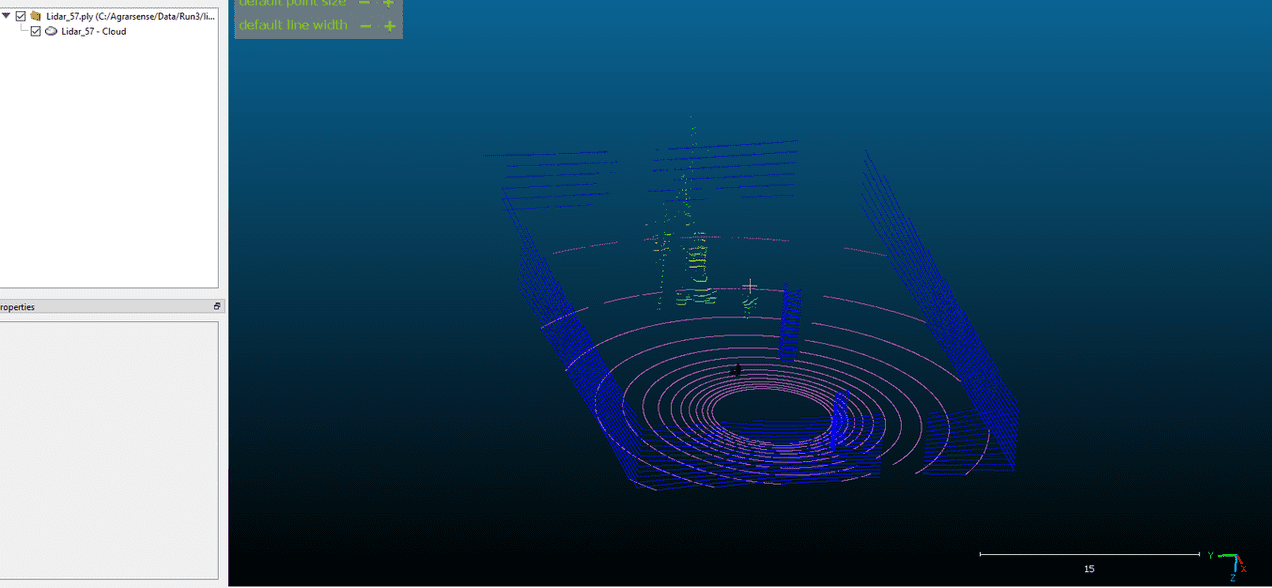
Saved semantic pointcloud visualized in CloudCompare software.
Camera sensors
Cameras are by far the most performance heavy sensors in the simulator. Each Camera sensor adds significant GPU load and minor/medium CPU load.
Each Camera sensor creates its own custom Unreal window where the camera view is rendered.
If you are using Lapland UAS fork of the Unreal Engine, you can minimize the Window which will continue rendering the camera view. If you using Unreal Engine from Epic Games launcher, minimizing the window is disabled because the camera would stop rendering. This is because Unreal Engine stops painting the Window when its minimized. You can also move and resize the window as you like. This will not affect the camera resolution or output when saving images to disk or sending image data to ROS, only the preview window image may stretch incorrectly. Closing the Custom camera window destroyes the sensor and its ROS topic.
All Camera sensors share same base Camera parameters, but all indivial cameras also has its own camera parameters, for example Depth camera has its own depth camera parameters but also the base camera parameters.
Base camera parameters:
| Parameter | Type | Default | Description |
|---|---|---|---|
PostProcessingEffects | bool | true | Enables or disables Post Process effects. |
Enable16BitFormat | bool | true | Enables 16-bit format. |
Width | int32 | 800 | Camera resolution width. |
Height | int32 | 600 | Camera resolution height. |
MaxViewDistanceInCmOverride | float | -1.0 | Camera max rendering distance in cm override |
UseHDR | bool | false | Enables/Disables HDR output, only for RGB camera |
FOV | float | 90.0 | Camera Field of View in degrees. |
TargetGamma | float | 2.2 | Camera gamma value. |
ShutterSpeed | float | 60.0 | Camera shutter speed. |
ISO | float | 100.0 | Camera ISO value. |
FocalDistance | float | 0.0 | Distance in which the Depth of Field effect should be sharp, in centimeters. |
DepthBlurAmount | float | 1.0 | Depth blur amount for 50%. |
DepthBlurRadius | float | 0.0 | Depth blur radius in pixels at 1920x resolution. |
DofMinFStop | float | 1.2 | Defines the minimum opening of the camera lens to control the curvature of the diaphragm. Set it to 0 to get straight blades. |
DofBladeCount | int32 | 5 | Defines the number of blades of the diaphragm within the lens (between 4 and 16). |
FilmSlope | float | 0.88 | Film slope. |
FilmToe | float | 0.55 | Film toe. |
FilmShoulder | float | 0.26 | Film shoulder. |
FilmBlackClip | float | 0.0 | Film black clip. |
FilmWhiteClip | float | 0.04 | Film white clip. |
ExposureMinBrightness | float | -10.0 | Auto-Exposure minimum adaptation. Eye Adaptation is disabled if Min = Max. |
ExposureMaxBrightness | float | 20.0 | Auto-Exposure maximum adaptation. Eye Adaptation is disabled if Min = Max. |
ExposureSpeedUp | float | 10.0 | Auto-Exposure speed-up in F-stops per second (should be greater than 0). |
ExposureSpeedDown | float | 1.0 | Auto-Exposure speed-down in F-stops per second (should be greater than 0). |
MotionBlurIntensity | float | 0.5 | Motion Blur intensity (0: off). |
MotionBlurMax | float | 5.0 | Maximum distortion caused by motion blur, in percent of the screen width (0: off). |
MotionBlurMinObjSize | float | 0.0 | Minimum projected screen radius for a primitive to be drawn in the velocity pass, as a percentage of the screen width (default: 0%). |
LensFlareIntensity | float | 1.0 | Brightness scale of image-caused lens flares (linear). |
BloomIntensity | float | 0.675 | Multiplier for all bloom contributions (0: off, >1: brighter). |
WhiteTemp | float | 6500.0 | White temperature. |
WhiteTint | float | 0.0 | White tint. |
ChromAberrIntensity | float | 0.0 | Scene chromatic aberration / color fringe intensity (in percentage). |
ChromAberrOffset | float | 0.0 | Normalized distance to the center of the framebuffer where the chromatic aberration effect takes place. |
Aperture | float | 4.0 | Defines the opening of the camera lens (aperture is 1/f-stop, larger numbers reduce the depth of field effect, default = 4.0). |
SaveImageToDisk | bool | false | Indicates whether to save sensor data to disk. |
SendDataToROS | bool | true | Indicates whether to send this camera data to a ROS topic. |
TargetFrameRate | float | 0.0 | Camera sensor target frame rate. 0.0 means every simulation frame, 30.0 means 30 frames per second etc. Targeting doesn't guarantee the simulation runs at the specified frame rate. |
UsePhysicLensDistortionEffect | bool | true | Should use camera physics lens distortion effect |
UseIceLensEffect | bool | false | Should use camera ice lens effect, simulation Weather parameters do not affect this, IceLensEffectStrength and IceLensEffectAngle do |
IceLensEffectStrength | float | 0.3 | Camera ice lens effect strength |
IceLensEffectAngle | float | 1.0 | Camera ice lens effect angle |
Note 1. SaveImageToDisk works asynchronously as is not guaranteed to be saved in the same frame. When SaveImageToDisk is set to true, separate camera_metadata.txt is also created to the same save location. This text file contains every image metadata in following format: image_name, X location, Y location, Z location, yaw rotation, pitch rotation, roll rotation
Note 2. Camera sensors should not see Lidar sensor particles even if Lidar sensor VisualizePointcloud is set to true. This is intended behaviour.
RGB camera
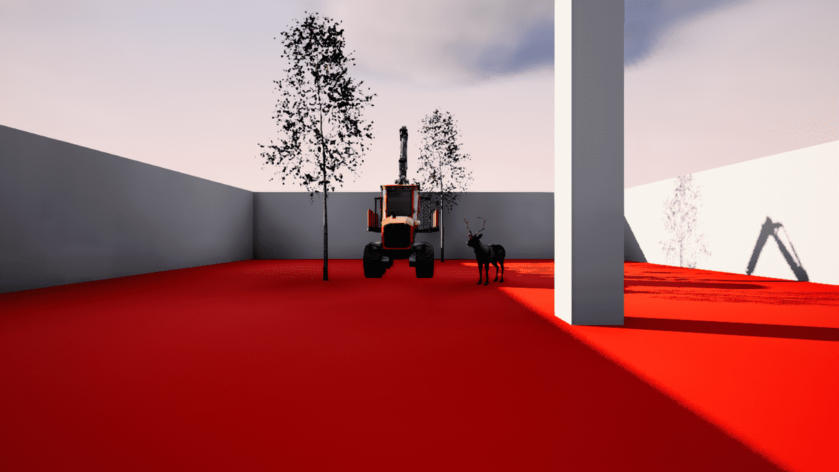
RGB camera acts as a regular camera capturing images from the scene.
This camera only has the base camera parameters. See above for parameters
Output image:
Depth camera
Depth Camera provides a raw data of the scene codifying the distance of each pixel to the camera to create a depth map of the elements.
Depth Camera parameters:
| Parameter | Type | Default | Description |
|---|---|---|---|
| ConvertToGrayscale | bool | false | Should image be converted to grayscale. |
| CameraParameters | FCameraParameters | Default Camera parameters | Camera parameters. |
Depth camera image where ConvertToGrayscale is set to false.
Output image:
Depth camera image where ConvertToGrayscale is set to true.
Output image:
DVS camera
A Dynamic Vision Sensor (DVS) or event camera is a sensor that works differently from a conventional camera. Instead of capturing images at a fixed rate, event camera measures changes of intensity.
DVS camera sends both converted Image to ROS Image topic and the raw DVS camera data as pointcloud2 message.
Note: When VisualizeDVSCamera is set to false, the sensor creates a single camera window without DVS visualization. When set to true, it opens a separate window to display the DVS camera output. The need for two windows arises from how the camera sensor reads pixel output. Reading, manipulating the pixels, and visualizing the output in one window causes flickering.
DVS Camera parameters:
| Parameter | Type | Default | Description |
|---|---|---|---|
| PositiveThreshold | float | 0.3 | Positive threshold C associated with an increment in brightness change (0-1). |
| NegativeThreshold | float | 0.3 | Negative threshold C associated with a decrement in brightness change (0-1). |
| SigmaPositiveThreshold | float | 0.0 | White noise standard deviation for positive events (0-1). |
| SigmaNegativeThreshold | float | 0.0 | White noise standard deviation for negative events (0-1). |
| RefractoryPeriodNs | int32 | 0 | Refractory period in nanoseconds. It limits the highest frequency of triggering events. |
| UseLog | bool | true | Indicates whether to work in the logarithmic intensity scale. |
| LogEps | float | 0.001 | Epsilon value used to convert images to the log scale. |
| SortByIncreasingTimestamp | bool | true | Should DVS events be ordered by increasing timestamps. Turning this to false will improve performance. |
| ParallelImageConversion | bool | true | Indicates whether to use ParallelFor for the DVS camera image grayscale conversion. |
| ParallelSimulation | bool | true | Indicates whether to use ParallelFor for the DVS camera simulation. |
| VisualizeDVSCamera | bool | true | Indicates whether to visualize DVS camera output in a separate window. |
| CameraParameters | FCameraParameters | Default Camera parameters | Camera parameters. |
Output image:

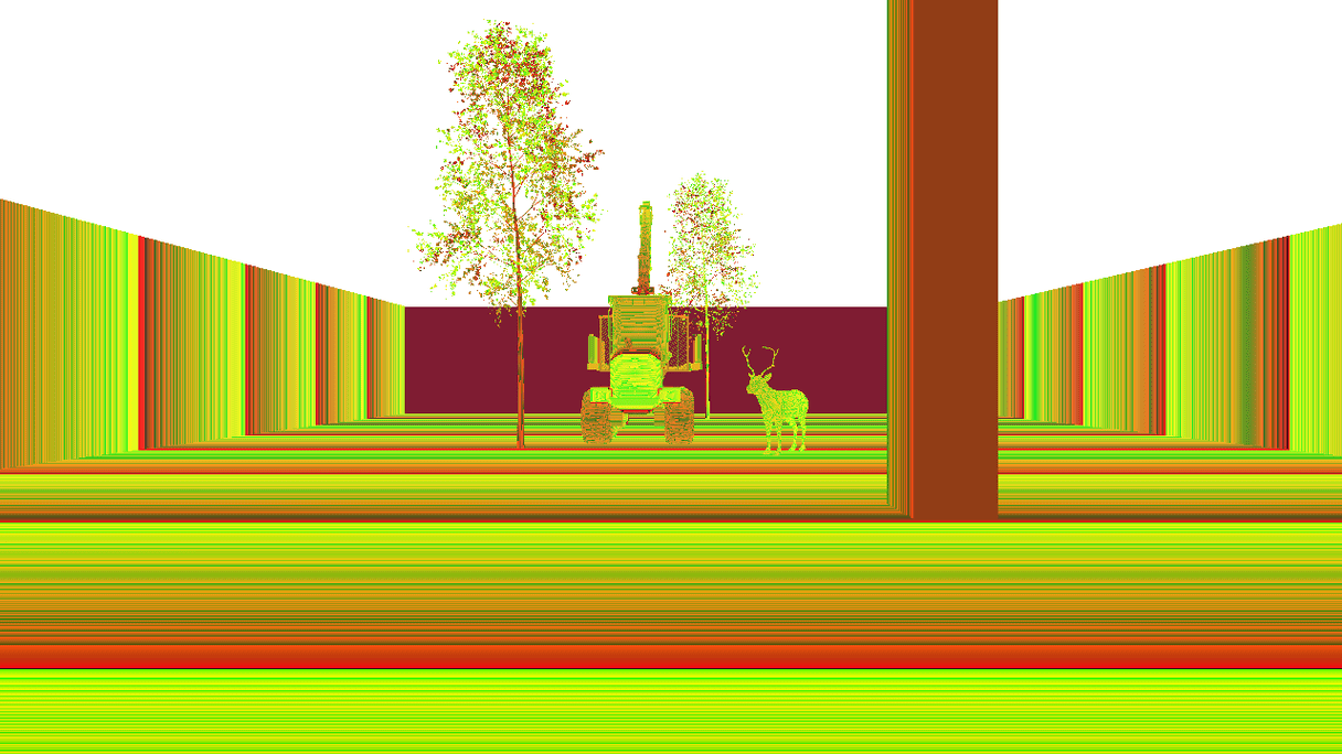
Semantic Segmentation Camera
This camera classifies every object in the view by displaying it in a different color according to its set stencil value.
Current limitations:
- Cannot see fire niagara asset due niagara component not supporting custom depth
Semantic colors and indexes are as follows:
| Label | RGB (R,G,B) | class/Label index |
|---|---|---|
| None | 0, 0, 0 | 0 |
| Terrain | 192, 96, 192 | 1 |
| Props | 128, 64, 128 | 2 |
| Human | 220, 20, 60 | 3 |
| Reindeer | 0, 0, 255 | 4 |
| Foliage | 107, 142, 35 | 5 |
| Birch | 0, 255, 0 | 6 |
| Pine | 0, 128, 0 | 7 |
| Spruce | 0, 192, 0 | 8 |
| Alder | 0, 255, 128 | 9 |
| Willow | 0, 255, 255 | 10 |
| Sky | 11, 255, 255 | 11 |
| Road | 169, 169, 169 | 12 |
| Building | 0, 0, 255 | 13 |
| Rocks | 139, 69, 19 | 14 |
| Deadwood | 160, 82, 45 | 15 |
| Drone | 0, 0, 142 | 16 |
| Harvester | 0, 0, 142 | 17 |
| Forwarder | 0, 0, 142 | 18 |
| Sensors | — | 19 |
| Snow | 255, 255, 0 | 20 |
| Leaves | — | 21 |
| Moose | 255, 140, 0 | 22 |
Output image:
You can change the semantic colors by defining colors in JSON format and passing it through ROS with following command:
Or by drag and dropping the json file to simulation main window (drag dropping a json file only works on Windows platform)

Instance Segmentation Camera
Each pixel encodes:
- Semantic class (label ID) in the Red channel (
R). - Instance ID split across Green (
G, low byte) and Blue (B, high byte).
Decoding formula
Output image:

Inspecting the image with python script shows the instance as:
class/Label index - Instance ID (4-1) meaning reindeer class/label index is 4 and this particular reindeer is the first instance ID. If we were to inspect the second reindeer in this image it would show as 4-2. See class/label index values above.

Current limitations:
- Only works on Nanite enabled meshes. Does not see other meshes like the landscape snow which is done with Virtual Heightfield Mesh.
- Only Trees, rocks, stumps are instance segmented in the simulator. Landscape grass types like grass, twigs, small branches on the ground are not instance segmented.
- Each class (label) can have maximum of 65535 instances.
- Doesn't support HISM/ISM components. Must be indivial static mesh components.
- Cannot see fire niagara asset due niagara component not supporting custom depth
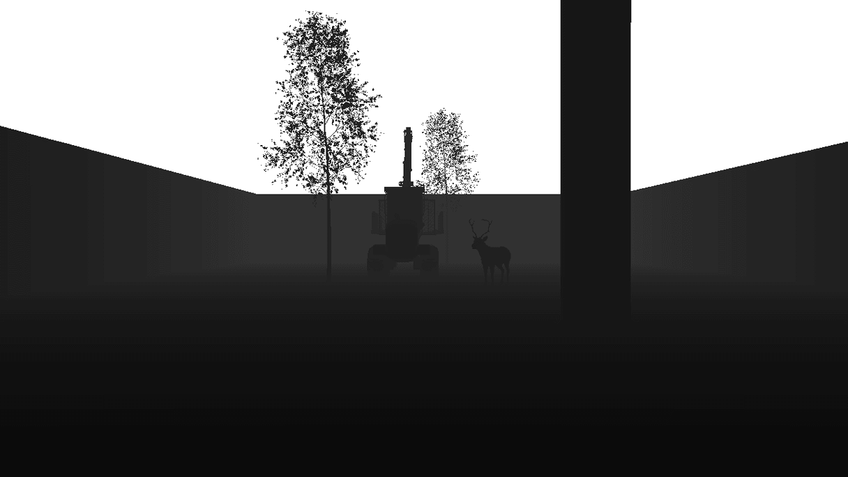
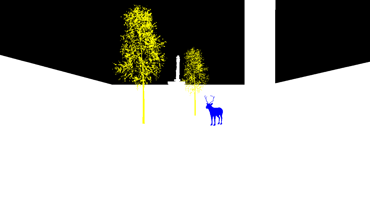
Thermal camera
The simulator offers simplified thermal camera where animals such as reindeer are marked with warm colors and everything else with cold colors.
Under the hood this sensor works similairly to semantic segmentation camera and uses post processing material and Unreal engine stencil value to determine how to color the objects, but with different color table.
Current limitations:
- Cannot see fire niagara asset due niagara component not supporting custom depth
Thermal Camera parameters:
| Parameter | Type | Default | Description |
|---|---|---|---|
| WarmColor | Vector4 | 1.0, 0.0, 0.0, 1.0 | Warm color |
| WarmColor2 | Vector4 | 1.0, 0.55, 0.0, 1.0 | Second warm color |
| ColdColor | Vector4 | 0.0, 0.07, 0.36, 1.0 | Cold color |
| ColdColor2 | Vector4 | 0.0, 0.11, 1.0, 1.0 | Second cold color |
| AllowCustomNoiseResolution | bool | false | Should allow custom noise resolution |
| WidthResolutionNoise | int32 | 1280 | Width noise resolution, only applies if AllowCustomNoiseResolution is true |
| HeightResolutionNoise | int32 | 720 | height noise resolution, only applies if AllowCustomNoiseResolution is true |
| CameraParameters | FCameraParameters | Default Camera parameters | Camera parameters. |
When AllowCustomNoiseResolution is set to true, you can modify WidthResolutionNoise and HeightResolutionNoise to create lower quality output to better simulate different kinds of camera sensors.
Below is a gif showing thermal camera output, first with AllowCustomNoiseResolution set to false and then AllowCustomNoiseResolution set to true with WidthResolutionNoise and HeightResolutionNoise set to 460 and 240.
Output image:

Spawning sensor
AGRARSENSE Simulator offers multiple ways for spawning sensors.
Terminology:
- World: Sensors are placed in a fixed position, unattached to any moving object.
- Vehicle: Sensors are mounted to a vehicle, tracking its movement.
- Spectator: Sensors are attached to the simulator's spectator actor, tracking its movement.
- Garage: A dedicated environment where you can focus exclusively on configuring and attaching sensors to a vehicle.
Spawning Sensors to World or to Vehicles through Asset Placement
Open Asset Placement
Spawning Sensors to World through JSON
The simulator allows spawning sensors to fixed position, unattached to any moving object.
You can spawn objects to World through JSON either:
A) Drag and drop json file(s) to Simulator window like below.
Note. Drag and drop only works on Windows platform at the moment.
B) Spawn json file through ROS
Publish message to the /agrarsense/in/commands topic in following format: SpawnObjects FULL_PATH/YOUR_JSON_FILE.json
Example json file to spawn rgb camera sensor. You can find more example .json files in ROOT/Agrarsense/Examples/ExampleJsonFiles directory. All of these can be drag and dropped to simulator window (Windows only) or spawned through ROS.
Spawning Sensors to Spectator camera through JSON
Spawning sensors to spectator Actor can only be done through JSON.
The only difference compared to Spawning Sensors to World through JSON is to add attachToSpectator: true field.
Spawning Vehicle with sensors through JSON
To spawn vehicle with sensor(s) you can use following json structure.
Spawning Sensors to Vehicle through Garage
Getting vehicle into the garage you can do either:
A) Right click the vehicle which will open up a context menu. In the Context menu, click on the 'Garage' option. After you exit the garage, vehicle will be teleported back to the previous location.
B) Open up the Vehicle Listing menu, and press the Garage icon button next to the vehicle name.
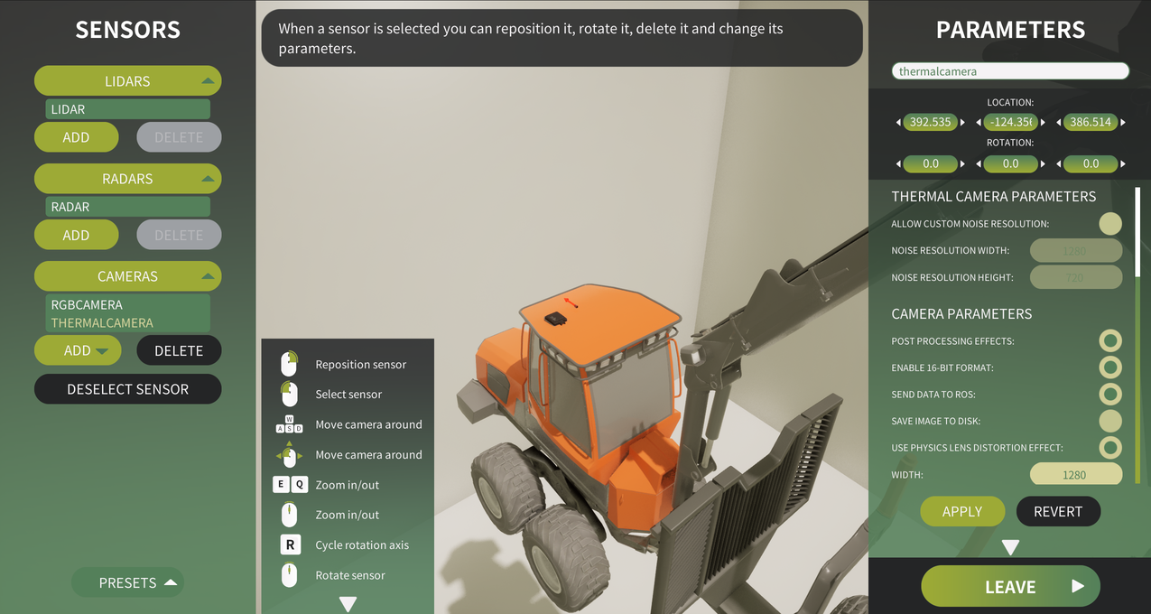
Garage user interface
Vehicle's sensors are listed on the left side. Lidars, radars and cameras are in separate lists. These lists can be closed/opened by clicking on the list header. Below the sensor lists is the Presets-button which will show the Presets-menu. Next to those is the guide for the controls. This guide can be closed by clicking on the arrow below the guide. On the right is the parameters menu which will open when a sensor has been selected either by clicking on the sensors on the list, or by adding a new one. This parameters menu can also be hidden with the arrow button below it. Below the parameters menu is the Leave-button which will leave the garage and teleport the vehicle back to its previous location.
Adding sensors in Garage
To add a sensor, click on one of the ADD-buttons below the sensor lists. After this right click on the vehicle to spawn the sensor to that location. The newly added sensor appears on the list and the parameters menu will open.
Selecting sensor and changing parameters in Garage
To select a sensor, you can either: A) Left-click the sensor 3D-model, or B) Click the sensor's name on the sensor lists
After selecting a sensor, the right side parameters menu will be populated with the selected sensor's data. To change the parameters, or the sensor's name, modify the values and press the APPLY-button which will save the input values to the sensor. If you don't want to save the new input values, press the REVERT-button. The revert will only revert the unsaved input values, and can't be used to revert saved values.
Removing sensors in Garage
To remove a sensor, select it from the list and press the DELETE-button. Deletion requires confirmation so you have to press it again after it comes enabled again.
Sensor presets in Garage
Click on the Presets-button to open up the presets menu. Here you can save current sensors configuration to a presets which can later be loaded from the user interface. Menu consists of a list which shows all the existing presets. Clicking the list item will select that preset.
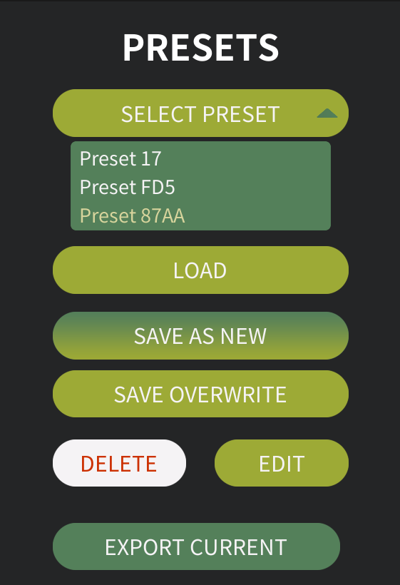
Options:
- Press the LOAD-button to replace current sensor configuration with this preset
- Press the "SAVE AS NEW"-button to save current sensors configuration to a new preset. A prompt will be shown to ask for the preset name
- Press the "SAVE OVERWRITE"-button to save current sensors configuration to selected preset overwriting the sensors data
- Press the DELETE-button to delete the preset (deletion requires confirmation click)
- Press the EDIT-button to edit the preset's name. A prompt will be shown to ask for the new name
- Press the "EXPORT CURRENT"-button to export the current sensors configuration (not the selected preset) to a JSON-file. A prompt will be shown to ask for the filename
Exporting Sensors and vehicles with sensors
The simulator supports exporting various elements to JSON files, complete with their current parameters. To export sensors or vehicles equipped with sensors, follow the steps outlined below.
All exported .json files are saved to the SIMULATION_ROOT/Data/ExportedJsonFiles/ directory.
Export through Garage
In the garage user interface Press the "EXPORT CURRENT"-button to export to a JSON-file. A prompt will be shown to ask for the filename.
Export through Developers Tools
You can toggle Developer Tools interface by clicking ctrl + F9 key combination at any point. From the you can click "Export Sensors" or "Export Vehicles" to export things.
Export through ROS command
Using Camera sensors to gather synthetic data (DataCapture)
The simulator enables the collection of synthetic camera data from specific locations by using a .json configuration file.
This feature can be used to gather synthetic RGB, Depth, Semantic Segmentation or Thermal camera data quickly. You can find more examples in the ExampleJsonFiles directory.
In the following example, a .json file is configured to spawn an RGB camera. The camera moves to each location listed under "points," captures a snapshot, and saves the image to disk. Once all points have been processed, the camera sensor is destroyed. You can spawn multiple cameras within the same .json file, just ensure that the "dataCapture" field is defined last.